They did their job. Hight is much more consistent now and runout is nonexistent. Also, the new spindle is sooooo quiet! Here is a closeup of a 39mm by 17mm circuit outline done with this setup.

As you can see, the bit consistently took the copper off without leaving burrs and the bit never went deep enough to dig into the glass fiber / epoxy, which dulls the bit. Another reason why you don't want to dig past the copper layer is because the bits for this kind of work are V shaped and would make the traces thinner the deeper they went. Also, when you dig in it just looks ugly. Anyways, I thought all my problems were solved... but it turns out I just got lucky. I have now identified a lot more problems.
First, let me explain my experiment setup. In order to waste as little material as possible I wanted to try something a lot smaller than I have tried in the past. I settled on an opto end-stop that I use on my mill and printer (thanks Zack). I can now say that choosing this board was brave. The traces are 16mil (0.4064mm) and the pads are 10mil (0.254mm) from each hole's edge to the edge of the pad. Still, this board should be obtainable and prove I will have no issues with SMT moving forward.
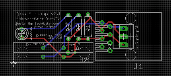
I attempted this board five times, using different settings. Six problems consistently surfaced, of which I will describe below.
1) PCB Thickness Tolerance
Problem:
I am still experiencing depth issues! I was under the impression that blank PCBs had a consistent thickness. I was wrong. The board I am working with varies in thickness from 1.49mm to 1.52mm randomly. This is enough to make the bit dig in, in some areas.
Solution:
Poul-Henning Kamp, a FreeBSD developer who dabbles in milling PCBs has considered this problem and has a solution. His solution entails grounding the board, turning off the spindle, and probing the board with the milling bit in a 4mm X 4mm grid. He then parses new Z values into the GCode based on this hight information. His unique solution cannot be directly used by me, but the concept could be applied.
I estimate it would take me 20 hours to write and test software / firmware to automate this task.
2) Bad Motor Coupling
Problem:
Refer to the following image.
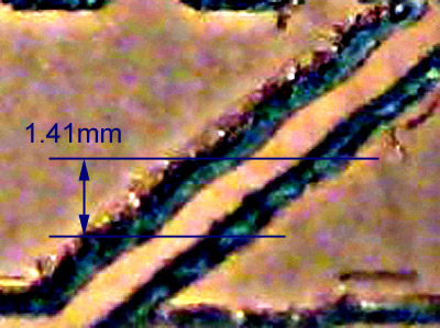
What you are looking at is a diagonal trace, enhanced and sharpened. As you can see, every 1.41mm the Y axis seems to slow and then speed up, resulting in a wave type effect. Inconsistencies like this can be really bad if they are in certain places of the design. They could result in an incomplete circuit, or a circuit that will fail. The cause is a bad motor coupling that is causing the motor to wobble, storing up energy and then releasing it once per revolution. The motor also looks a little off axis, or it could be that the drive-shaft is slightly bent.
Solution:
I need to redesign the part and print a new one. I also need to make sure the motor is being held in the right position and that the shaft is straight.
It may take me a few prints to get the coupling right, so I will estimate it taking me 3 hours not counting printing time.
3) Not Round

Problem:
These pads are suppose to be perfectly round and they're not. I double-checked the gcode through NCPlot and the code looks fine.
Solution: ??
I'm not sure on this one. Either this will be fixed when I fix the Y axis or there is something else at play.
4) Incomplete / Grounded Pad

Problem:
Two of the pads have a little bridge connecting them to the rest of the copper. Again, I checked the gcode and this should not have happened. What's odd is it's the same two pads on all five goes. If this was the aforementioned Y axis issue then I should have seen some randomness.
Solution: ??
Again, not sure. I think it may have to do with play from starting and stopping quickly in a small area. I am planning on running a few tests to eliminate possibilities.
5) Drifting Hole

Problem:
When drilling after milling I'm finding that the holes work their way to a milled groove.
Solution:
Pcb-gcode has a feature to tap the holes with the milling bit after milling. I think that will eliminate this issue.
6) Inconsistent Traces

Problem:
As you can see, the trace on the left is thinner than the trace on the right. This should not be because they are both 16mil traces. Again, I double-checked the gcode.
Solution: ??
I'm crossing my fingers that this is the Y axis again. I will just have to see.
So... it looks like it will take me +25 hours to solve these problems. I mention this because I want to make it clear that if you are planning on milling PCBs then plan on spending a lot of time getting it to work. Granted, some of these problems would not be faced if I had just bought a mill, but there are still a lot of things to get right.


